ECU MODS / REPAIR:
sample text
- Toyota / 4A-GE
- Car page
16V:
Mod Boards
The 16V ECU unfortunately can’t* be reprogrammed, so enthusiasts often resort to custom piggyback boards, modified ROMs, or small add-on modules to adjust fueling and timing. Even TRD and other
major tuners produced custom piggybacks for these ECUs back in the ’80s and ’90s.
*Note: Some individuals have reportedly reverse-engineered the firmware and claim to support reflashing, but so far no fully verified or
publicly working solution other than piggyback boards exists.
I made some non-mcu boards myself before i upgraded to an standalone.
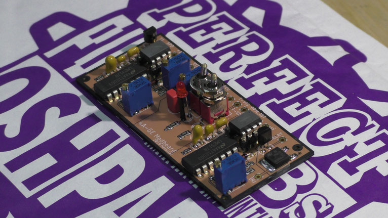
Oldschool Modboard made by me : Adjustable T-VIS RPM, Fault Code LED, Adjustable MAP and CLT Signal offset, an Logic and an 5A Output (Speed Chime and/or RPM Switch) and IGF (Ignition Coil Field/Fault Signal) Simulator to use other Coils and Drivers
First version of my adjustable clock-speed board. Changing the processor’s frequency alters ignition timing, fueling, and the RPM limit — effectively letting you "fine"-tune the engine without a
piggyback or standalone ECU.
It’s a bit messy but also a simple way to tweak the factory tune.
Managed to get a clean 104 kW on an Bigport with just slight head and intake work done
20V:
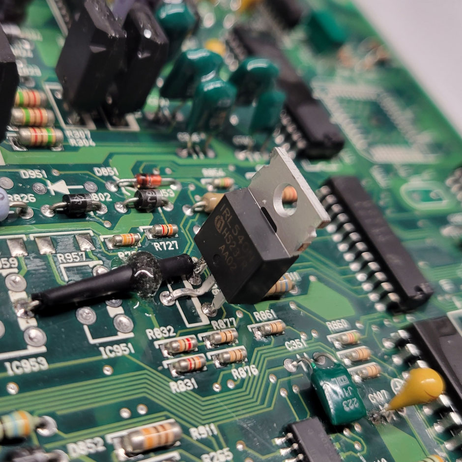
-VVT Transistor Replacement and Upgrade
The OEM transistor (NEC 2SD1694) on Blacktop ECUs is a common failure point.
It’s rated at 3 A @ 60 V. Thats enough for the VVT solenoid which draws around 1.3 A, but it cant handle the inductive kick when switching off.
There is a 1Ω Resistor and a protection diode (MPG06J) on the pcb, but it seems like it doesent help at all, leading to repeated transistor failures.
Note:
Some people claim the 20V uses variable control for valve timing — it doesn’t. There’s no PWM, just a simple ON/OFF signal.
While PWM control might be possible with a standalone ECU for finer tuning, there’s little reason to do so. It’s also unclear whether the solenoid (specifically its internal spring) can tolerate
PWM operation. The pulley itself would likely be fine, as it moves relatively slowly — full activation reportedly takes about 1.5–3 seconds.
Anyways, i replaced it with an IRL540N logic-level MOSFET (100 V, 36 A) — total overkill, but intentionally so. It’s avalanche-rated and much more robust. I also added a 10 kΩ gate
pulldown just to be safe (under the heatshrink, secured with epoxy).
See image.
-PCB Recap:
I used those for my ECU (89661-1A860) but this will most likely correct for other ones. I didnt write down the amount of each caps needed, but buying in 10x is cheaper anyway.
HINT: PCB is a 4 Layer one with huge ground and power planes internally. Use a desoldering gun or an iron with a big thermal mass, otherwise the now 30 year old plating/tracks can lift of the Board due to excess and too long heat.
| MOUSER Part Number | Manufacturer Part | Description | Type | Specifications |
|---|---|---|---|---|
| 667-EEU-FC1C221 | EEU-FC1C221 | Aluminum Electrolytic Capacitor - Radial Leaded | Electrolytic | 220µF 16V |
| 647-UPW1E221MPD1CC | UPW1E221MPD1CC | Aluminum Electrolytic Capacitor - Radial Leaded | Electrolytic | 25V 220µF |
| 667-EEU-FR1H100B | EEU-FR1H100B | Aluminum Electrolytic Capacitor - Radial Leaded | Electrolytic | 50VDC 10µF ±20%, Lead Spacing 5mm |
| 647-UPM1J470MPD1TA | UPM1J470MPD1TA | Aluminum Electrolytic Capacitor - Radial Leaded | Electrolytic | 47µF 63V, AEC-Q200 |
| 647-UPW2A330MPD6TD | UPW2A330MPD6TD | Aluminum Electrolytic Capacitor - Radial Leaded | Electrolytic | 33µF 100V ±20%, AEC-Q200 |
| 581-TAP105J035CRW | TAP105J035CRW | Tantalum Capacitor - Solid, Axial Leaded | Tantalum | 35V 1µF ±5%, ESR = 8Ω |
| 581-TAP475K035CCS | TAP475K035CCS | Tantalum Capacitor - Solid, Axial Leaded | Tantalum | 35V 4.7µF ±10%, ESR = 3Ω |
| 581-TAP106K035CRW | TAP106K035CRW | Tantalum Capacitor - Solid, Axial Leaded | Tantalum | 35V 10µF ±10%, ESR = 2Ω |
| 581-TAP154K035CCS | TAP154K035CCS | Tantalum Capacitor - Solid, Axial Leaded | Tantalum | 35V 0.15µF ±10%, ESR = 2.1Ω |
| 581-TAP224K035CCS | TAP224K035CCS | Tantalum Capacitor - Solid, Axial Leaded | Tantalum | 35V 0.22µF ±10%, ESR = 1.7Ω |
| 581-TAP225K035CCS | TAP225K035CCS | Tantalum Capacitor - Solid, Axial Leaded | Tantalum | 35V 2.2µF ±10%, ESR = 5Ω |
| 581-TAP335K035CCS | TAP335K035CCS | Tantalum Capacitor - Solid, Axial Leaded | Tantalum | 35V 3.3µF ±10%, ESR = 4Ω |
| 647-UPJ1J101MPD | UPJ1J101MPD | Aluminum Electrolytic Capacitor - Radial Leaded | Electrolytic | 63V 100µF, 10×20mm, ±20%, 5mm LS |
-O2 Heater code bypass
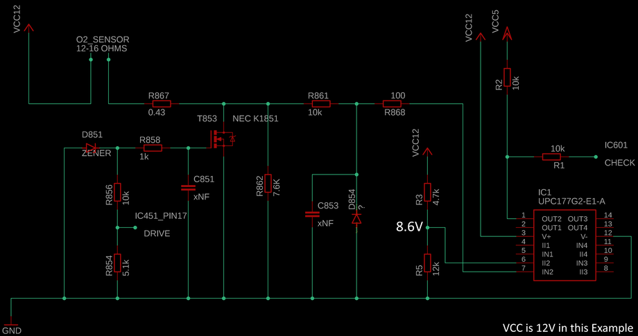
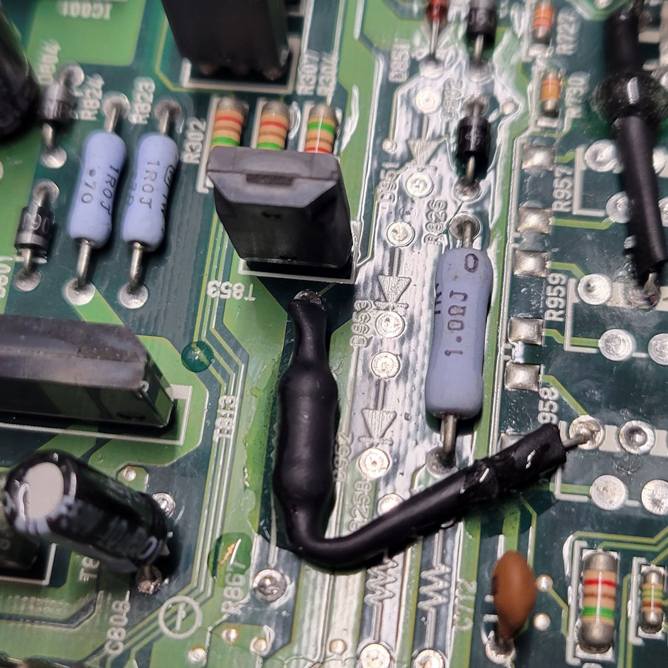
This is the O₂ sensor heater circuit from a Blacktop ECU (and probably the Silvertop too).
I’m using a wideband sensor with its own heater control, so the OEM heater output can’t be used.
A 14 Ω / 25 W dummy resistor would work, but it’s inefficient and wasteful.
Reverse-engineering shows the ECU’s heater check is actually very simple.
Current flows through R867 (a fusible resistor) and T853 (NEC K1851), while R862 (7.6 kΩ) pulls the transistor’s drain down if the heater is open.
R861, R868, C853, and D854 just handle filtering and protection.
The uPC177G2 comparator checks this node against a fixed 8.6 V reference (set by R3 /
R5).
If the node is above 8.6 V, the heater is considered OK; if not, it triggers a fault.
Since R862 pulls down with 7.6 kΩ, a resistor of about 2 kΩ to +12 V raises the voltage to
roughly 9.5 V — enough to pass the check without generating heat.
Connect the 2 kΩ resistor between +12 V and the heater pin or the heater sense node (the drain side of T853 ).
Fun fact:
The ECU only tests the heater before it switches it on (at startup).
Once active, the drain node stays near 0 V, meaning it can’t detect a heater failure while driving!
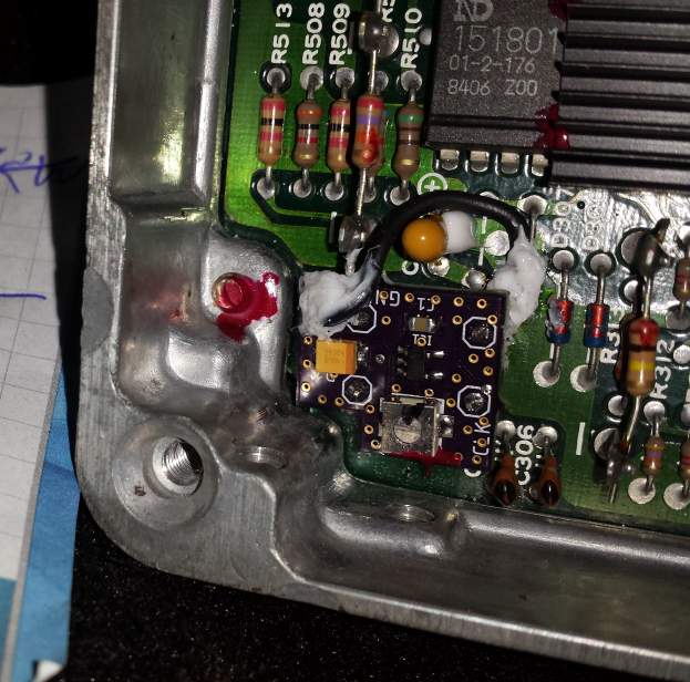
Below is a picture of the mod. I removed R867 and connected a 2K resistor between the transistor and a connection to "+B" on the Ecu (Not "BATT") on the pcb.